
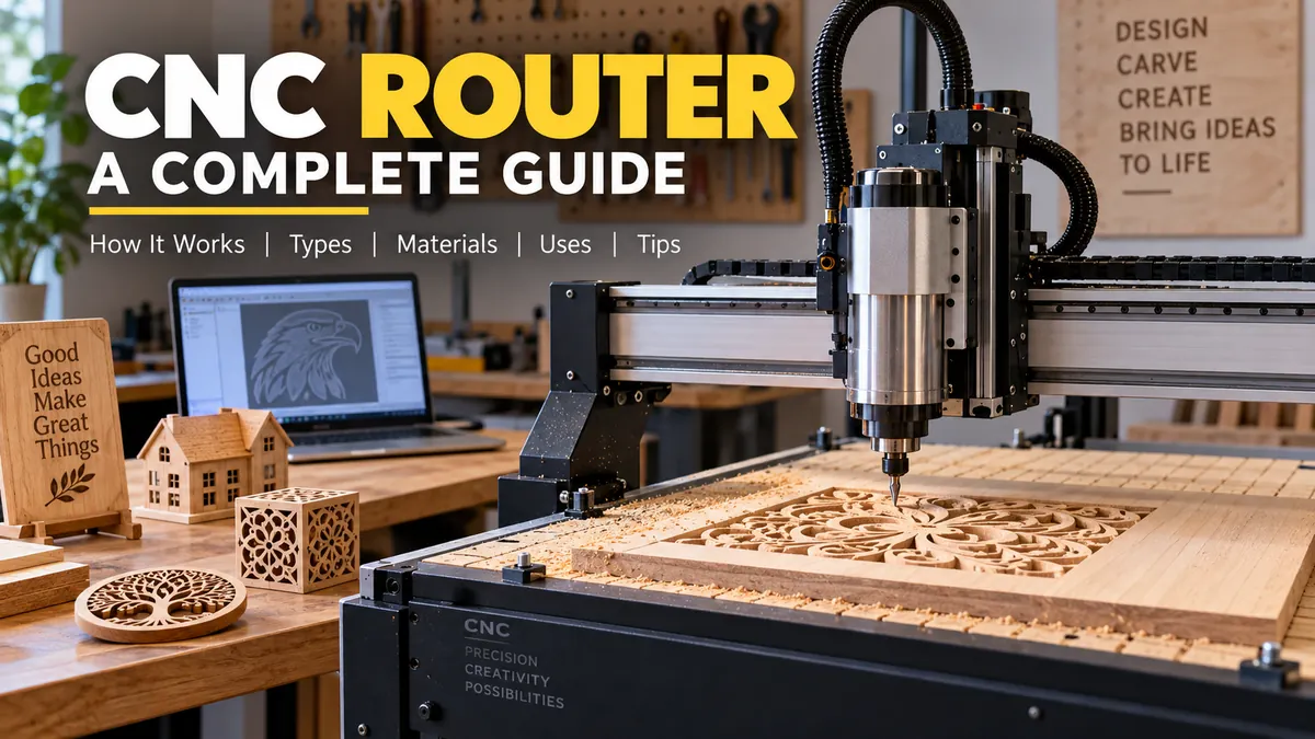

A cnc router can turn a digital drawing into a precisely cut sign, cabinet panel, furniture component, plastic part, or detailed carving with very little manual tool guidance. Instead of pushing a handheld router through material, the operator programs where the cutting tool should move.
That automation is what makes CNC routing valuable for both one-off projects and repeatable production. Yet good results depend on much more than simply loading a design and pressing Start.
A cnc router is a computer-controlled cutting machine that moves a rotating cutting tool along programmed X, Y, and Z coordinates. It uses CAD/CAM software and G-code to cut, carve, engrave, drill, pocket, and shape materials such as wood, MDF, plywood, plastics, foam, composites, and, on suitable machines, some soft metals.
What Is a cnc router?
CNC stands for Computer Numerical Control. A CNC router is therefore a router whose movements are directed by numerical instructions rather than by a person manually guiding the cutting head.
Most machines have a flat worktable with a gantry spanning the cutting area. A spindle or router motor mounted on the gantry holds the cutting tool. Motors move that tool along different axes while a controller interprets the machining program.
The three basic axes are:
- X-axis: movement from side to side
- Y-axis: movement from front to back
- Z-axis: vertical movement that controls cutting depth
Coordinated movement across these axes allows the cutter to follow straight lines, curves, pockets, contours, lettering, and complex three-dimensional toolpaths.
A conventional handheld router can perform some of the same cutting operations, but the operator controls its movement. With CNC routing, software determines the toolpath and the machine repeats that path automatically.
This distinction matters most when a project requires identical parts. Once a properly designed program and setup have been proven, the same geometry can be reproduced without manually tracing every part.
CNC routing is a subtractive process
A CNC router belongs to the family of subtractive manufacturing technologies.
The process starts with a solid sheet, board, block, or other workpiece. A rotating cutter removes unwanted material until the required geometry remains.
That differs fundamentally from additive manufacturing such as 3D printing, where material is deposited layer by layer.
How Does a cnc router Work?
A CNC router workflow typically moves through five stages:
- Create or import the design.
- Generate machining toolpaths.
- Convert the toolpaths into machine-readable instructions.
- Secure and zero the workpiece.
- Run the machining program.
Each stage affects the finished part.
1. The part is designed in CAD software
The process normally begins with CAD, or computer-aided design.
CAD software defines the geometry the machine eventually needs to produce. Depending on the job, this might be simple text for a sign, a cabinet component with holes and pockets, or a detailed 3D relief.
Designs can also originate in vector graphics software or other applications, provided the geometry can be transferred into the machining workflow.
2. CAM creates the toolpaths
A drawing alone does not tell a CNC machine how to cut.
CAM, or computer-aided manufacturing, determines how the cutting tool should interact with the design. The user specifies operations and machining parameters such as cutter selection, cutting depth, stepdown, stepover, spindle speed, feed rate, entry strategy, and toolpath direction.
CAM can generate operations for:
- Profile cutting
- Pocketing
- Engraving
- V-carving
- Drilling
- Surfacing
- 2.5D machining
- 3D contouring
The CAM program then converts those operations into instructions the CNC controller understands.
3. G-code tells the machine where to move
The resulting machine program is commonly expressed as G-code.
G-code contains commands describing positions, movement, feed rates, and other machine actions. The controller reads these instructions and commands the motors accordingly.
This creates a workflow that can be summarized as:
Design → CAD → CAM → toolpath → G-code → controller → machine movement → finished part
One common beginner mistake is assuming G-code itself creates the design. It does not. It is primarily the set of instructions used to execute the machining strategy.
4. The workpiece is secured and zeroed
Before machining begins, the material must be held securely.
Common workholding methods include:
- Clamps
- T-slot fixtures
- Screws
- Vacuum tables
- Jigs and fixtures
- Double-sided workholding methods for appropriate light-duty jobs
The operator also establishes the work coordinate zero, giving the machine a reference point from which programmed coordinates are measured.
Poor workholding can ruin an otherwise correct program. If the stock moves during a cut, dimensional accuracy, edge quality, and safety can all be compromised.
5. The machine follows the programmed path
Once the correct tool is installed, the stock is secured, coordinates are established, and the program has been checked, machining can begin.
The spindle rotates the cutting tool while the machine moves it through the programmed coordinates.
The machine does not independently decide whether a feed rate, cutting depth, or bit is appropriate. Those decisions still depend on the operator and the machining setup.
Quick Takeaway: CNC automation improves repeatability, but it does not replace machining knowledge. Tool selection, workholding, feeds and speeds, chip evacuation, machine rigidity, and toolpath strategy still determine whether a cut succeeds.
Main Parts of a CNC Router
Although desktop and industrial machines differ considerably in size and construction, most CNC routers contain the same fundamental systems.
Frame and gantry
The frame provides structural support, while the gantry carries or supports the moving cutting assembly.
Rigidity matters because cutting forces can cause structural deflection. Excessive flex can produce vibration, chatter, dimensional errors, and poor surface finishes.
Large industrial machines commonly use substantial steel structures, while smaller machines may use aluminum extrusion or other lighter construction.
Spindle or router motor
The spindle rotates the cutting tool.
Some hobby machines use a trim router as their cutting motor. More advanced machines commonly use dedicated CNC spindles with collets and variable-speed control.
High spindle speeds are particularly useful when machining materials such as wood and plastics. Routers are generally designed around faster spindle operation and lighter cutting loads than conventional metalworking mills.
Collet and toolholder
The collet grips the cutter in the spindle.
Common dedicated CNC spindle systems include ER-style collets such as ER11, ER16, ER20, and ER32, although the exact system depends on the spindle.
A clean, correctly sized collet is critical. Dirt, wear, incorrect installation, or excessive tool stick-out can increase runout and shorten tool life.
Stepper or servo motors
The machine requires motors to position its axes.
Stepper motors are common on hobby and lower-cost CNC systems. Servo motors are frequently found on higher-performance industrial machines.
Open-loop stepper systems typically move according to commands without continuously verifying actual motor position. Closed-loop systems can incorporate feedback to detect or correct positioning differences, depending on their design.
Linear motion and drive system
Motors need a mechanical system to convert rotation into controlled linear movement.
Common mechanisms include:
- Lead screws
- Ball screws
- Rack-and-pinion drives
- Belt drives
- Linear rails and guides
Ball screws can provide low-backlash, precise motion, while rack-and-pinion systems are often practical on large machines where axes must travel long distances quickly.
Backlash is unwanted lost motion when an axis reverses direction. Excessive backlash can affect circles, pockets, joints, and other features requiring accurate directional changes.
Controller
The CNC controller interprets machine instructions and coordinates axis movement.
It effectively acts as the bridge between the machining program and the machine’s motors, spindle, limit switches, and other hardware.
Worktable and spoilboard
The worktable supports the material.
Woodworking CNC routers often use a replaceable spoilboard, frequently made from MDF, above the machine bed. The cutter can pass slightly into this sacrificial surface when cutting through sheet material without damaging the main machine table.
Spoilboards are periodically resurfaced so their top remains parallel to the machine’s cutting plane.
Vacuum table
Industrial routers frequently use vacuum workholding.
A vacuum table draws material against the machine bed, which is particularly useful for large sheet goods such as MDF, plywood, and plastic.
Vacuum holding strength depends on factors such as pump capacity, leakage, surface area, material porosity, and zoning.
Dust and chip collection
Routing can produce large quantities of chips and fine dust.
A dust shoe surrounding the cutting area can connect to an extraction system. Effective collection improves visibility and machine cleanliness while reducing airborne particulate contamination.
Certain materials require much more careful dust control than ordinary woodworking. Composite machining, for example, can generate hazardous fine particles, making appropriate extraction, filtration, and personal protective equipment especially important.
What Materials Can a cnc router Cut?
Material capability depends on far more than whether the cutter can physically penetrate the stock.
Machine rigidity, spindle power and speed, cutter geometry, feeds and speeds, cooling, lubrication, workholding, and chip evacuation all matter.
Wood and engineered wood
Woodworking is one of the most common CNC routing applications.
Typical materials include:
- Hardwood
- Softwood
- Plywood
- MDF
- Particleboard
- Laminated panels
A router can cut cabinet components, furniture parts, decorative panels, joinery, doors, signs, mouldings, and carved artwork.
CNC routers can also create joinery such as mortises and tenons.
Plastics
Many plastics machine effectively on CNC routers, including suitable grades of:
- Acrylic
- HDPE
- Polycarbonate
- PVC
- Acetal
- Other machinable thermoplastics
Plastic introduces a different problem from wood: heat.
If cutter geometry, spindle speed, or feed rate is poorly matched, chips may melt and weld back onto the tool or workpiece. The objective is generally to form and evacuate clean chips rather than rub the material.
Foam
Foam places relatively low cutting loads on a machine, making routers useful for patterns, prototypes, props, packaging components, molds, and large 3D forms.
Tooling foam, EPS, and XPS are among the materials encountered in routing applications.
Composites
CNC routers can machine certain fiberglass, carbon-fiber, and laminated composite materials.
Tool wear and dust management become especially important. Abrasive fibers can shorten cutter life, while fine composite dust may require specialized extraction and PPE.
Can a CNC router cut aluminum?
Yes, some CNC routers can machine aluminum, but capability depends heavily on the machine and setup.
A rigid router with appropriate tooling, secure workholding, suitable chip load, controlled depth of cut, effective chip evacuation, and appropriate lubrication or cooling can machine certain aluminum work.
However, being able to cut aluminum is not the same as being optimized for heavy metal machining.
Routers are generally better suited to relatively light machining of softer metals, whereas CNC mills are designed around the rigidity and torque required for demanding metal removal.
What about steel?
Conventional woodworking-style CNC routers are generally not the appropriate machines for machining steel.
Steel requires much greater rigidity, appropriate spindle characteristics, tooling, chip management, and often coolant systems. A CNC milling machine is normally the appropriate platform for regular precision machining of steel, stainless steel, titanium, and similar materials.
CNC Router Bits and What They Do
The cutting tool directly affects edge quality, cutting forces, chip evacuation, and the geometry that can be produced.
There is no universal bit for every CNC job.
Straight bits
Straight cutters provide straightforward material removal and can be useful for grooves, pockets, and general routing.
More specialized spiral tools are often preferred when chip evacuation or edge quality is critical.
Upcut bits
An upcut spiral moves chips upward and away from the cut.
That makes chip evacuation effective, particularly for deeper slots and pockets. The trade-off is that upward cutting forces can lift fibers at the top surface of wood-based materials.
Downcut bits
A downcut spiral pushes cutting forces downward.
It can produce a cleaner top edge on plywood and veneered materials, but chip evacuation can be more difficult in deep cuts because chips are driven toward the bottom.
Compression bits
A compression cutter combines upward and downward cutting geometries.
When used at an appropriate depth, it can help produce clean edges on both faces of laminated or veneered sheet goods, making compression tooling particularly useful in cabinet and furniture production.
V-bits
V-shaped cutters are used for V-carving, lettering, decorative engraving, and chamfer-like features.
Common included angles vary, and the appropriate angle depends on the desired width and depth of the engraved feature.
Ball-nose end mills
A ball-nose cutter has a rounded tip.
It is widely used for 3D reliefs, sculpted surfaces, molds, and smooth contour machining. A roughing tool may first remove the majority of the material before a smaller ball-nose cutter makes the finishing passes.
Surfacing bits
Surfacing cutters remove material across a broad area.
They are commonly used to flatten or resurface spoilboards and can also flatten suitable workpieces.
O-flute cutters
Single-flute or O-flute cutters are commonly associated with plastics and can also be useful in some aluminum-routing applications because their geometry provides generous space for chip evacuation.
Feeds, Speeds, and Chip Load
A CNC router can have an accurate frame and excellent software yet still produce poor cuts if its machining parameters are wrong.
Three terms matter immediately.
Spindle speed
Spindle speed describes how quickly the cutting tool rotates, usually in revolutions per minute (RPM).
Feed rate
Feed rate is how quickly the cutting tool moves through the workpiece.
Chip load
Chip load is the approximate thickness of material removed by each cutting edge during each revolution.
A simplified relationship is:
Chip load = Feed rate ÷ (RPM × number of flutes)
For example, increasing RPM without increasing feed can reduce chip load. If the cutter stops producing healthy chips and begins rubbing, heat can increase and tool life or surface quality can suffer.
The correct settings depend on cutter diameter, flute count, material, spindle capability, machine rigidity, depth of cut, tool stick-out, and other conditions.
Manufacturer tooling data is a much better starting point than copying a random feed-and-speed setting from an unrelated machine.
CNC Router Software: CAD, CAM, and Machine Control
New users sometimes treat CNC software as one application, but the workflow can involve several separate functions.
CAD software
CAD creates the geometry.
Depending on the work, designs may be 2D vectors, dimensional mechanical parts, or full 3D models.
CAM software
CAM takes that geometry and creates machining operations.
The user selects tools and defines parameters such as:
- Cut depth
- Stepdown
- Stepover
- Feed rate
- Spindle speed
- Profile direction
- Pocket strategy
- Tabs
- Ramps
- Finishing passes
The software calculates the resulting toolpaths.
Post-processor
Different controllers can expect different command formats.
A post-processor converts CAM output into the form required by a specific controller or machine configuration. Choosing the wrong post-processor can generate commands the machine does not interpret as intended.
Machine-control software
Control software sends or executes the machining program and provides functions such as jogging, homing, coordinate zeroing, feed control, and machine-status monitoring.
The exact software stack varies considerably among hobby, prosumer, and industrial systems.
3-Axis, 4-Axis, and 5-Axis CNC Routers
Not every router is limited to three-axis machining.
3-axis CNC router
A standard 3-axis router controls X, Y, and Z movement.
This arrangement handles an enormous range of work, including:
- Sheet cutting
- Cabinetry
- Signs
- Pockets
- Engraving
- Drilling
- 2.5D parts
- 3D relief carving
For many woodworking and fabrication applications, three axes are sufficient.
4-axis CNC router
A fourth axis commonly introduces rotary movement.
Instead of machining only a flat workpiece, a rotary axis can rotate a cylindrical or irregular part, allowing work around its circumference.
Typical applications include columns, furniture legs, decorative posts, and cylindrical carving.
5-axis CNC router
Five-axis machines provide additional angular movement so the cutting tool can approach a workpiece from multiple directions.
They are useful for complex molds, composite components, sculptural work, aerospace-related structures, and parts that would otherwise require several separate setups.
The added flexibility comes with greater machine cost, programming complexity, setup requirements, and operator training.
Common CNC Router Uses
The large work area and ability to process sheet materials explain why CNC routers appear across several industries.
Cabinetry and furniture
A full-size machine can process sheet goods for cabinet boxes, doors, drawer components, shelving, furniture panels, and joinery.
Common industrial router sizes include beds designed around full sheets, including approximately 4 × 8 ft and 5 × 10 ft configurations.
Sign making
CNC routing can create:
- Dimensional lettering
- Logo panels
- Acrylic components
- Wooden signs
- Plastic signs
- Engraved plaques
- Routed channels
V-carving and profile cutting are particularly common sign-making operations.
Decorative carving
Complex patterns that would take substantial time to reproduce manually can be programmed and repeated.
Applications include architectural panels, wall art, decorative doors, moldings, relief carvings, and ornaments.
Prototyping
Foam, plastic, wood, and other easy-to-machine materials make routers useful for physical prototypes and design models.
Musical instruments
CNC routing can help machine instrument bodies, neck components, cavities, templates, and other repeatable features.
Composite and plastic trimming
Industrial machines can automate trimming of formed plastic and composite components. CNC routers are used in areas ranging from furniture and signage to boat building and other manufacturing applications.
cnc router vs CNC Mill: What Is the Difference?
The machines share the principle of moving a rotating cutter through programmed coordinates, but their mechanical priorities differ.
| Feature | CNC Router | CNC Mill |
|---|---|---|
| Primary strength | Large-area, high-speed machining | Rigid, precision machining |
| Typical materials | Wood, plastics, foam, composites | Metals and engineering materials |
| Work envelope | Often large | Usually smaller for comparable cost |
| Spindle behavior | Generally higher speed | Often greater low-speed torque |
| Structure | Commonly gantry-based | Typically much heavier and more rigid |
| Sheet processing | Excellent | Usually impractical |
| Heavy metal cutting | Limited | Designed for it |
| Typical work | Signs, panels, furniture, carvings | Brackets, housings, molds, precision parts |
A CNC router is optimized for moving rapidly over relatively large work areas and machining softer materials. A CNC mill prioritizes structural rigidity and controlled metal removal.
This is why machine selection should begin with the material, part dimensions, geometry, and required tolerance, rather than with the CNC label alone.
CNC Router vs Laser Cutter
These machines can also overlap in applications, especially signage and sheet fabrication, but their cutting methods are fundamentally different.
A router uses physical contact between a rotating cutting edge and the material.
A laser uses focused energy to cut or engrave.
Routing can create pockets, rebates, drilled features, contoured edges, and significant 3D geometry. A laser is especially effective for narrow kerfs, intricate 2D profiles, and non-contact engraving on compatible materials.
Material behavior also differs. A router produces chips and mechanical cutting forces, whereas laser cutting creates a heat-affected process and requires attention to fumes, fire risk, and material compatibility.
Neither technology universally replaces the other.
Accuracy, Precision, and Repeatability
Three concepts are often mixed together.
Accuracy describes how closely the machine reaches the intended dimension or position.
Repeatability describes how consistently it can return to the same position or reproduce the same result.
Resolution refers to the smallest commanded or measurable movement within a system and does not automatically equal real-world machining accuracy.
Real part accuracy depends on the entire system:
- Frame rigidity
- Linear guides
- Ball screws or rack-and-pinion drives
- Backlash
- Motor and controller performance
- Spindle runout
- Cutter deflection
- Tool condition
- Workholding
- Material movement
- Machine calibration
- Temperature
- Cutting forces
- CAM strategy
This is why a very small theoretical motor step does not prove that a machine can cut parts to the same tolerance.
Routers are generally less rigid than purpose-built CNC mills. Published comparisons commonly place practical router tolerances for wood and plastic work looser than those of precision milling machines, although actual capability varies substantially by machine, material, setup, and measurement method.
Workholding Matters More Than Beginners Expect
One of the fastest ways to ruin a CNC job is to let the material move.
Workholding must resist both lateral and vertical cutting forces while keeping clamps and fixtures away from the programmed toolpath.
Vacuum workholding
Vacuum tables are excellent for large panels, but small parts can lose holding force as surrounding material is cut away.
Tabs, an onion-skin finishing strategy, or alternative fixturing may therefore be necessary.
Mechanical clamps
Clamps provide strong, straightforward holding but require careful positioning. A cutter colliding with a metal clamp can damage the tool, spindle, workpiece, or machine.
Tabs
Tabs leave small connections between a cut part and the surrounding stock. After machining, the part is removed and the tabs are trimmed.
They are especially useful when profile cutting small components from sheet material.
What Is Tramming?
Tramming means aligning the spindle so its rotational axis is properly oriented relative to the machine table.
A spindle that is noticeably out of tram can leave ridges when a wide surfacing cutter passes across the workpiece.
This problem becomes particularly obvious when resurfacing a spoilboard.
Before blaming software or the cutter for an uneven surfaced finish, experienced operators check table flatness, machine geometry, spindle alignment, and cutter runout.
Common CNC Router Mistakes
Most early CNC problems are not caused by mysterious software bugs. They usually come from basic setup issues.
Using the wrong cutter
A tool designed for one material may perform badly in another.
Match cutter geometry, diameter, flute count, and material to the job.
Cutting too deeply in one pass
Aggressive depth of cut increases tool load, machine deflection, and the chance of lost steps, chatter, or broken cutters.
Multiple controlled passes are often more reliable.
Poor chip evacuation
Recutting chips generates additional heat and can damage both the cutter and surface finish.
This is particularly important with plastics and aluminum.
Incorrect zero position
If the program assumes Z-zero is at the material surface but the machine was zeroed somewhere else, the resulting cutting depths will be wrong.
Always know where the CAM program expects X, Y, and Z zero.
Ignoring cutter diameter
The centerline of a cutting tool cannot simply follow every finished edge.
CAM software compensates for cutter radius when generating inside and outside profile paths.
Running a program without checking it
Before cutting valuable stock, verify:
- Correct program
- Correct units
- Correct tool
- Correct work offset
- Secure workholding
- Safe clearance
- Appropriate spindle speed
- Appropriate feed rate
- Toolpath orientation
- Expected cutting depth
A simulation or controlled test run can catch expensive mistakes before the cutter reaches the material.
CNC Router Safety
Computer control does not make a router harmless.
A spindle may rotate at very high speed, cutters can break, workpieces can come loose, and routing can generate substantial dust, chips, noise, and debris.
Operators should use appropriate eye and hearing protection, control dust effectively, keep loose clothing and hair away from moving equipment, and follow the machine manufacturer’s operating and emergency-stop procedures.
Never reach into a machine while its cutting system is moving.
Dust deserves particular attention. Wood dust is not simply a housekeeping problem, and machining certain composites creates additional particulate hazards. Suitable extraction and filtration should be chosen for the material being machined.
The machine should also have a readily accessible emergency-stop system, and operators should understand what it does before beginning a job.
What Determines CNC Router Performance?
A bigger spindle or higher advertised feed rate does not automatically produce better parts.
Overall performance comes from the complete machine system.
Key factors include:
- Frame rigidity
- Gantry stiffness
- Working area
- Spindle power and usable RPM range
- Collet and spindle runout
- Linear guides
- Drive mechanism
- Backlash
- Stepper or servo system
- Controller quality
- Acceleration capability
- Workholding
- Dust/chip management
- Tooling
- Software compatibility
For real-world work, the material and required part size should come first.
A large machine designed for full plywood sheets has different priorities from a compact system intended for detailed engraving, while a shop making tight-tolerance metal components generally needs a milling machine rather than simply a more powerful woodworking router.
Desktop, Hobby, and Industrial CNC Routers
CNC routers range from compact desktop systems to large production machines.
Desktop machines
Desktop systems are useful for learning, engraving, prototypes, and small parts.
Their smaller footprint makes them practical where space is limited, but their work envelope, rigidity, spindle capacity, and production rate can be more limited.
Hobby and prosumer machines
Larger hobby machines can handle substantial woodworking projects and, depending on their construction, may support sophisticated CAD/CAM workflows.
They often represent a middle ground between entry-level desktop equipment and industrial machinery.
Industrial CNC routers
Production routers may include:
- Large vacuum beds
- High-power spindles
- Servo drives
- Automatic tool changers
- Tool-length measurement
- Multiple vacuum zones
- Dust extraction
- Automated loading or unloading
- Multi-spindle configurations
- 4-axis or 5-axis capability
These features reduce manual intervention and increase throughput, particularly when many different tools or large numbers of parts are involved.
Automatic Tool Changers
An automatic tool changer (ATC) allows a CNC router to switch cutters during a program without requiring the operator to manually replace each tool.
Consider a cabinet component requiring a compression cutter for profiling, a smaller end mill for pockets, and a drill for holes.
Without an ATC, the operator may need to stop the process and change tools manually. With a properly configured automatic system, the machine can perform these changes as part of the program.
The benefit is not simply convenience. Tool-changing automation can significantly improve workflow consistency when jobs require multiple operations.
How to Understand a CNC Router Before Using One
A beginner does not need to master every G-code command before making a first part, but several concepts should be understood first.
Learn them in this order:
- Machine coordinates and axes — understand X, Y, and Z.
- Homing and work zero — know how the machine establishes position.
- Basic CAD — create clean geometry.
- CAM and toolpaths — understand profiles, pockets, drilling, and engraving.
- Router bits — know why different cutters behave differently.
- Feeds and speeds — learn the relationship between RPM, feed rate, and chip load.
- Workholding — prevent material movement.
- Simulation and verification — inspect the job before machining.
- Dust and chip control — keep the cutting zone clear and manage material hazards.
- Emergency procedures — know how to stop the machine safely.
Start with simple material and straightforward geometry rather than an elaborate 3D project.
A basic profile or pocket teaches coordinate setup, cutter selection, workholding, feeds and speeds, CAM, and zeroing without introducing unnecessary complexity.
Final Thoughts on the cnc router
A cnc router combines computer control, CAD/CAM software, G-code, a high-speed spindle, precision motion systems, and cutting tools to automate subtractive machining. Its strongest applications are typically wood, MDF, plywood, plastics, foam, composites, signage, furniture, cabinetry, prototypes, and other large-format or relatively soft-material work.
Understanding the workflow is more useful than simply memorizing machine specifications. A successful part depends on the entire chain: accurate geometry, sensible toolpaths, the correct cutter, secure workholding, proper feeds and speeds, good chip or dust removal, accurate zeroing, and a machine suited to the material.
For someone learning CNC routing, the most useful next step is to master one simple 3-axis project from CAD through CAM and machining. Once that complete workflow makes sense, more advanced operations such as V-carving, 3D contouring, rotary-axis work, automatic tool changing, and production machining become much easier to understand.
