
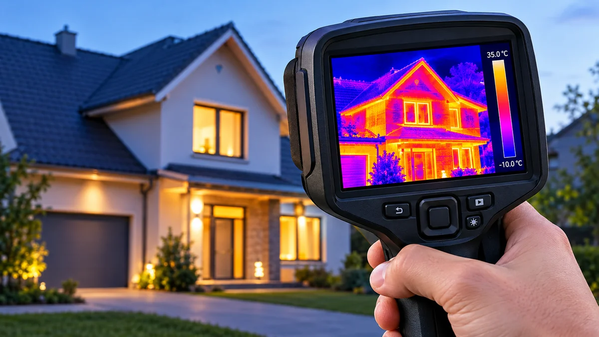

A wall can look perfectly normal while hiding a moisture problem. An electrical connection may appear undamaged even as it overheats. A thermal imaging camera helps reveal temperature patterns that ordinary eyesight cannot detect.
A thermal imaging camera is a device that detects infrared radiation emitted by objects and converts it into a visual representation of apparent surface temperatures. Also called an infrared camera or thermal camera, it helps identify heat differences in buildings, electrical systems, machinery, and other environments without requiring direct physical contact.
Unlike an ordinary camera, which records visible light, a thermal camera measures infrared energy. This distinction makes it useful in darkness, but it also introduces limitations that users need to understand before interpreting an image.
What Is a thermal imaging camera?
A thermal imaging camera is a non-contact imaging instrument that measures infrared radiation from surfaces and produces a thermogram—a visual map of apparent temperature differences.
Most thermal cameras display warmer and cooler areas using contrasting colors. For example, warmer surfaces may appear yellow, orange, or white, while cooler surfaces appear blue, purple, or black. The exact appearance depends on the selected color palette.
The technology is used in building inspections, preventive maintenance, electrical troubleshooting, firefighting, scientific research, and industrial monitoring.
Thermal imaging vs. regular photography
The key difference is the type of electromagnetic radiation each camera detects.
| Feature | Thermal imaging camera | Regular camera |
|---|---|---|
| Radiation detected | Infrared radiation | Visible light |
| Main output | Temperature-related image | Photographic image |
| Works in darkness | Yes, for detectable thermal contrast | Usually requires illumination |
| Measures temperature | Radiometric models can estimate it | No |
| Sees through ordinary walls | No | No |
| Typical uses | Inspection, diagnostics, monitoring | Photography, documentation |
Thermal imaging does not reveal the inside of solid walls. Instead, it shows surface temperature patterns that may indicate something happening behind them.
How Does a thermal imaging camera Work?

Thermal cameras translate detected infrared energy into a visual temperature pattern.
All objects with temperatures above absolute zero emit thermal radiation. The amount and wavelength distribution of that radiation depend on temperature and surface properties.
A thermal camera detects this energy and processes it into an image.
Step 1: Infrared radiation reaches the lens
The camera collects infrared radiation emitted and reflected by surfaces in its field of view.
Many common uncooled thermal cameras operate in the long-wave infrared (LWIR) band, approximately 8–14 micrometers.
Unlike ordinary glass lenses, which transmit visible light, thermal cameras often use specialized optical materials such as germanium.
Step 2: The infrared detector senses energy
The infrared detector converts incoming radiation into an electrical signal.
A common detector technology is the microbolometer, an uncooled sensor containing a grid of temperature-sensitive elements.
When infrared radiation reaches these elements, their electrical properties change. The camera measures these changes to estimate the received infrared energy.
Other thermal imaging systems use cooled photon detectors, which can offer greater sensitivity and faster response for specialized scientific and industrial applications.
Step 3: Image processing converts signals into a thermogram
The camera processes the detector readings, applies calibration information, and assigns colors or grayscale values to different apparent temperatures.
A thermogram is the resulting thermal image.
For radiometric cameras, the system can also calculate temperature estimates for individual pixels or measurement regions.
Step 4: The display highlights temperature differences
The image appears on the camera screen or a connected device.
An inspector might observe a hot electrical terminal, a cold area around a window frame, or an unusually warm bearing housing.
However, the camera does not automatically determine the cause of those temperature differences. Proper interpretation requires understanding the equipment, materials, and environmental conditions.
Types of Thermal Imaging Cameras
Thermal imaging systems differ in detector technology, physical design, temperature measurement capabilities, and intended applications.
Handheld thermal imaging cameras

Handheld cameras are widely used by electricians, building inspectors, maintenance technicians, and HVAC professionals.
They typically combine an infrared sensor, display, rechargeable battery, and temperature analysis features in a portable housing.
Smartphone thermal cameras

Smartphone thermal cameras connect to compatible mobile devices or incorporate dedicated thermal sensors.
They offer portable thermal visualization for basic inspection and troubleshooting.
Models such as FLIR ONE and Seek Thermal Compact illustrate this category, although sensor resolution, compatibility, and measurement capabilities vary by version.
Fixed thermal cameras
Fixed-mounted thermal imaging systems continuously monitor machinery, electrical installations, production lines, or other designated areas.
They can be integrated with industrial automation, alarms, and condition-monitoring software.
These systems are useful when temperatures need to be tracked repeatedly rather than inspected occasionally.
Drone-mounted thermal cameras

Thermal sensors mounted on unmanned aerial vehicles support inspections of rooftops, solar installations, industrial facilities, and large outdoor areas.
They can cover locations that would otherwise require scaffolding, elevated work platforms, or extensive walking inspections.
Drone thermal images require particular care because distance, wind, viewing angle, surface reflections, and changing solar exposure can influence results.
Cooled and uncooled thermal cameras
| Characteristic | Uncooled camera | Cooled camera |
|---|---|---|
| Common detector | Microbolometer | Cooled photon detector |
| Cooling requirement | No cryogenic cooler | Usually requires cooling |
| Complexity | Generally lower | Generally higher |
| Typical applications | Building and maintenance inspections | Research, long-range imaging, specialized monitoring |
| Sensitivity | Depends on sensor design | Can achieve very high sensitivity |
| Maintenance | Generally simpler | Cooling system adds complexity |
Uncooled cameras are common in everyday inspection work because they offer a practical balance of portability, performance, and cost.
Cooled systems are typically reserved for demanding applications requiring specific spectral bands, sensitivity, or imaging speed.
Common Applications of Thermal Imaging Cameras
Thermal imaging is useful wherever unusual temperature differences can reveal operating conditions, energy losses, or possible defects.
1. Building inspections and heat loss detection

Building inspectors use infrared thermography to identify temperature patterns associated with:
- Missing or uneven insulation
- Air leakage around doors and windows
- Thermal bridges in walls and roofs
- Possible moisture intrusion
- Heating and cooling distribution problems
For example, a poorly insulated section of an exterior wall may appear colder than surrounding areas during winter.
However, temperature patterns alone cannot prove that insulation is missing. Differences in solar heating, airflow, construction materials, and indoor conditions may produce similar images.
A proper building survey considers the indoor-outdoor temperature difference and may combine thermal imaging with moisture meters or blower-door testing.
2. Electrical inspections and overheating detection

Electrical maintenance teams use thermal cameras to locate components operating at unexpectedly high temperatures.
Potential inspection targets include circuit breakers, terminals, busbars, transformers, cables, and distribution panels.
An unusually hot connection may indicate increased resistance, poor contact, overload, or another electrical problem.
A meaningful inspection compares similar components operating under similar loads. A heavily loaded circuit may naturally run warmer than a lightly loaded one.
Thermal imaging should be performed by appropriately qualified personnel. Electrical panels can contain dangerous energized components, and a camera does not make an unsafe inspection procedure safe.
3. HVAC troubleshooting
Heating, ventilation, and air-conditioning systems depend on effective heat transfer and airflow.
Thermal imaging can help identify uneven radiator temperatures, abnormal heating patterns, poorly insulated ductwork, and temperature differences around air outlets.
It may also reveal suspicious temperature patterns associated with restricted airflow or malfunctioning equipment.
A thermal image is a diagnostic clue, not a substitute for refrigerant pressure measurements, airflow testing, or other appropriate HVAC procedures.
4. Mechanical equipment and predictive maintenance
Motors, pumps, bearings, gearboxes, and other mechanical components generate heat during operation.
A bearing running significantly hotter than comparable bearings may warrant investigation for lubrication problems, friction, excessive loading, or developing mechanical wear.
Thermal monitoring is particularly useful when maintenance teams record baseline images and compare equipment under consistent operating conditions.
This approach supports condition-based maintenance, where inspections help determine when additional testing or service may be necessary.
5. Solar panel inspections

Thermal cameras can identify unusual temperature distributions across photovoltaic modules.
Potential findings include localized hot spots, damaged cells, electrical connection issues, and patterns associated with shading or module faults.
Inspection conditions matter. Solar irradiance, wind, viewing angle, electrical load, and reflections can affect thermal results.
A suspicious thermal pattern should be evaluated alongside electrical measurements and the manufacturer’s inspection guidance.
6. Firefighting and search operations
Firefighters use specialized thermal imaging cameras to help identify heat sources, locate people under suitable conditions, and assess conditions in smoke-filled environments.
Thermal cameras may improve visibility when ordinary cameras are ineffective, although performance varies with smoke density, water vapor, obstructions, and environmental temperatures.
Fire-service devices are designed for demanding operational conditions and may be evaluated using requirements such as NFPA 1801.
Research from the National Institute of Standards and Technology (NIST) has examined thermal sensitivity, image contrast, spatial resolution, and effective temperature range for firefighting cameras.
NIST
+1
Thermal imaging supplements established firefighting procedures; it cannot reliably reveal every hidden hazard.
7. Wildlife observation and environmental research
Thermal imaging helps researchers detect temperature contrasts between animals and their surroundings, particularly in low-light conditions.
Applications include wildlife surveys, habitat studies, and certain ecological monitoring activities.
Detection is influenced by vegetation, distance, weather, the animal’s exposed surface temperature, and sensor resolution.
A thermal camera generally cannot identify an animal’s species from temperature alone.
Important Thermal Imaging Camera Specifications
Understanding camera specifications is essential for interpreting performance claims.
Infrared resolution
Thermal resolution describes the number of infrared detector pixels, not the resolution of an accompanying visible-light camera.
Common detector configurations include:
| Infrared resolution | Total thermal pixels | General capability |
|---|---|---|
| 80 × 60 | 4,800 | Basic thermal pattern recognition |
| 160 × 120 | 19,200 | General inspection tasks |
| 256 × 192 | 49,152 | More detailed thermal visualization |
| 320 × 240 | 76,800 | Detailed inspection work |
| 640 × 480 | 307,200 | Higher-detail professional imaging |
These are examples rather than universal performance categories.
Higher infrared resolution can help identify smaller features at a given distance, but lens quality, focus, detector sensitivity, and measurement geometry also matter.
Digital enlargement cannot recreate thermal details that the detector never captured.
Thermal sensitivity (NETD)
Noise Equivalent Temperature Difference, or NETD, describes a detector’s ability to distinguish small temperature differences under specified test conditions.
NETD is commonly expressed in millikelvin (mK).
For example:
- 100 mK corresponds to 0.10°C.
- 50 mK corresponds to 0.05°C.
- 30 mK corresponds to 0.03°C.
A lower NETD generally indicates better thermal sensitivity when comparing measurements under equivalent conditions.
However, thermal sensitivity is not the same as temperature measurement accuracy. A camera can detect small differences while still reporting an inaccurate absolute temperature.
Temperature measurement range
The measurement range indicates the temperatures a camera is designed to estimate.
A camera intended for building inspections may have different measurement capabilities from one designed for furnaces, molten materials, or industrial processes.
A broad range is not automatically superior. The useful range depends on the application and the accuracy achieved within it.
Measurement accuracy
Temperature accuracy describes how closely a reported value agrees with the actual surface temperature under specified conditions.
Manufacturers may express accuracy as a fixed temperature tolerance, a percentage of the reading, or whichever tolerance is greater.
Real-world accuracy also depends on emissivity, reflections, distance, atmospheric conditions, focus, and the size of the measurement target.
Field of view and spatial resolution
Field of view (FOV) determines the angular area captured by the camera.
A wide-angle lens covers more of a scene, while a narrower lens provides a closer view of distant objects.
Instantaneous Field of View (IFOV) describes the angular area associated with an individual detector element.
For accurate temperature measurement, the target generally needs to occupy more than a single detector pixel. The required target size depends on the camera’s measurement optics and spot-size specifications.
Focus and image fusion
Some thermal cameras use fixed-focus lenses, while others offer manual or automatic focusing.
Correct focus improves detail and can be critical for accurate measurements of small objects.
Certain systems also combine thermal information with visible-light imagery. For example, FLIR’s MSX image enhancement technology adds visible-edge details to help users recognize equipment and structural features.
Image fusion improves interpretation, but it does not increase the native infrared detector resolution.
Understanding Thermal Images and Color Palettes

Ironbow or rainbow paletteMultiple colors help distinguish temperature regions.

Grayscale paletteBrightness represents relative apparent temperature.
Thermal images commonly use several display palettes.
Ironbow: Uses a progression of dark, purple, red, orange, and yellow tones to emphasize thermal differences.
White Hot: Displays relatively warmer areas as lighter shades and cooler areas as darker shades.
Black Hot: Reverses that relationship, making warmer areas darker.
Rainbow: Uses multiple contrasting colors to separate apparent temperature ranges.
A common misunderstanding is that a red region always represents a dangerous temperature.
In reality, colors often depend on the camera’s automatically selected temperature scale. A surface at 35°C could appear bright yellow in one image and dark purple in another.
For reliable comparisons, examine the temperature scale and use consistent settings rather than judging colors alone.
What Affects Thermal Imaging Accuracy?
Thermal imaging is based on measurable physical principles, but several factors influence the accuracy of surface temperature estimates.
Emissivity
Emissivity describes how efficiently a surface emits thermal radiation compared with an ideal blackbody at the same temperature.
Values range from 0 to 1.
Approximate examples include:
| Material or surface | Typical emissivity |
|---|---|
| Human skin | 0.98 |
| Water | 0.98 |
| Matte painted surfaces | Around 0.90–0.95 |
| Oxidized metal | Highly variable |
| Polished aluminum | Often below 0.10 |
These values are illustrative. Surface condition, temperature, wavelength, and viewing angle can change emissivity.
Shiny metals can reflect radiation from nearby objects, causing the camera to display a misleading temperature.
FLIR’s thermography guidance explains why emissivity and reflected apparent temperature must be considered when interpreting measurements.
Flir
+1
Reflected apparent temperature
A reflective surface may show the infrared radiation of surrounding objects rather than its own true temperature.
For example, polished metal can reflect a nearby heater or even the person holding the camera.
Changing the viewing angle and using appropriate measurement techniques can help identify these reflections.
Distance and atmospheric conditions
Infrared radiation can be absorbed or scattered as it travels through the atmosphere.
Humidity, airborne particles, and distance may affect the signal reaching the detector.
The impact is especially relevant for longer-range measurements and demanding industrial applications.
Environmental influences
Sunlight, wind, rain, and recent heating or cooling can change surface temperatures.
A roof exposed to direct sunlight may display a different thermal pattern from the same roof after sunset.
For building inspections, timing and environmental conditions are often as important as the camera itself.
What Can a Thermal Imaging Camera See Through?
Thermal imaging is sometimes described as the ability to see through objects. This is misleading.
Most ordinary thermal cameras detect radiation from the visible surfaces of objects, not from hidden spaces behind opaque materials.
| Material | Can a typical LWIR thermal camera see through it? |
|---|---|
| Drywall | No |
| Concrete | No |
| Ordinary window glass | No |
| Wood | No |
| Metal | No |
| Some thin plastic films | Sometimes, depending on material and wavelength |
| Smoke | Sometimes, depending on density and composition |
| Fog or heavy rain | Performance can be significantly reduced |
Can thermal cameras see through walls?
No. A conventional thermal imaging camera cannot directly see people, pipes, or objects through an ordinary wall.
However, concealed features may influence the wall’s surface temperature.
For example, a warm pipe inside a wall might produce a detectable surface pattern if sufficient heat reaches the wall surface.
That pattern is indirect evidence, not an image of the pipe itself.
Can thermal cameras see through glass?
Most long-wave infrared cameras cannot see through ordinary window glass.
Instead, they primarily detect radiation emitted and reflected by the glass surface.
The optical behavior of glass varies with wavelength, so specialized infrared systems operating in other spectral bands can behave differently.
NIST Publications
Can thermal cameras see in complete darkness?
Yes. Passive thermal cameras do not require visible illumination because they detect infrared radiation.
However, detecting an object still requires sufficient thermal contrast, adequate resolution, and a suitable line of sight.
Can thermal imaging detect water leaks?
It can identify temperature anomalies associated with moisture, but it does not directly detect water molecules or confirm a leak.
Evaporation may cool a wet surface, while moisture can also alter heat transfer through building materials.
Confirmation generally requires a moisture meter, visual inspection, or other testing.
How to Use a thermal imaging camera Correctly
A systematic inspection produces more meaningful results than simply pointing the camera at a surface.
- Define the inspection objective. Determine whether you are looking for heat loss, overheating, uneven temperature distribution, or another condition.
- Check the environment. Consider sunlight, wind, ambient temperature, humidity, and recent equipment operation.
- Set appropriate measurement parameters. For radiometric measurements, configure emissivity, reflected apparent temperature, and other applicable settings.
- Focus on the target. Ensure that the relevant surface occupies enough pixels for meaningful analysis.
- Choose a suitable temperature scale. Avoid changing the scale unnecessarily when comparing images.
- Compare similar conditions. Electrical components should be compared under similar loads; building surfaces should be assessed with environmental conditions in mind.
- Capture thermal and visible images. Record the location, operating conditions, and measurement settings.
- Verify unusual findings. Use appropriate follow-up testing before diagnosing a defect or recommending corrective work.
Common mistakes to avoid
One frequent mistake is treating the hottest visible region as the most serious problem.
A properly functioning component may naturally operate at a higher temperature than surrounding equipment.
Another mistake is comparing images taken under different conditions without accounting for those differences.
A third is using thermal imaging as the sole evidence of moisture, insulation failure, or electrical damage.
Reliable thermography depends on context, repeatability, and verification.
Thermal Imaging vs. Night Vision
Thermal imaging and night vision are related but different technologies.
Traditional image-intensifier night vision amplifies available light, including some near-infrared illumination.
Thermal imaging detects radiation associated with the temperature of surfaces.
| Feature | Thermal imaging | Image-intensifier night vision |
|---|---|---|
| Primary detection | Thermal infrared radiation | Available visible and near-infrared light |
| Requires ambient light | No | Generally yes, or an illuminator |
| Shows temperature differences | Yes | No |
| Shows ordinary visual details | Limited | Often better |
| Works in total darkness | Yes | Requires auxiliary illumination |
| Performance through smoke | Sometimes useful | Often limited |
Digital night vision systems may use infrared illuminators to operate in darkness. These should not be confused with passive thermal cameras.
Thermal imaging is particularly useful for detecting heat contrast, while night vision can provide more recognizable visual details when sufficient illumination is available.
Advantages and Limitations of Thermal Imaging
Thermal imaging offers several practical advantages:
- Non-contact observation of surface temperature patterns
- Detection of thermal differences invisible to human eyesight
- Operation without visible light
- Faster inspection of large surface areas
- Support for preventive maintenance and troubleshooting
- Visual documentation of changing thermal conditions
However, the technology also has important limitations.
It cannot directly see through ordinary walls, diagnose the cause of every hot spot, or reliably measure reflective surfaces without appropriate correction.
Lower-resolution cameras may miss small defects, particularly at longer distances.
Environmental conditions can influence results, and the colors displayed in a thermogram are not independently meaningful without the temperature scale.
Thermal imaging is most effective as part of a broader inspection process rather than as a standalone diagnostic method.
Thermal Imaging Safety and Professional Standards
Infrared thermography is a passive measurement technique. A conventional thermal camera receives radiation rather than projecting harmful imaging radiation onto the subject.
The main safety risks usually arise from the environment being inspected.
Electrical systems, industrial machinery, hot surfaces, elevated work locations, and fire scenes can all present serious hazards.
Relevant professional references include:
- ISO 18434-1: Condition monitoring and diagnostics of machines using thermography.
- ISO 6781 series: Infrared methods related to assessing building thermal performance.
- NFPA 1801: Requirements associated with thermal imagers used by emergency services.
- ASTM thermography standards: Test and inspection methods for particular applications.
Training organizations such as the Infrared Training Center offer thermography education, while certification programs may reference ISO 18436-7 for personnel qualification in thermography-based machine condition monitoring.
Standards and certification requirements depend on the application, jurisdiction, and inspection scope.
A camera operator should understand both the imaging instrument and the physical system being examined.
The Future of Thermal Imaging Technology
Thermal imaging continues to develop through improvements in sensor manufacturing, image processing, connectivity, and automated analysis.
Smaller uncooled detectors have helped make thermal imaging practical in compact instruments and mobile devices.
Higher-resolution sensors and improved optics allow more detailed observation of distant or small targets.
Automated image analysis can help identify thermal anomalies across repeated inspections. Machine-learning systems may classify patterns or flag deviations from established operating baselines.
However, automated classification does not eliminate the need for physical verification. A detected anomaly may arise from normal operation, reflections, environmental changes, or an actual defect.
Connected thermal monitoring systems can also record temperature trends over time, making them useful for industrial condition monitoring and research.
The greatest benefit comes from combining better imaging hardware with sound measurement practices.
Final Thoughts
A thermal imaging camera makes otherwise invisible surface temperature differences easier to observe and analyze.
Its applications extend from building energy assessments and electrical inspections to industrial maintenance, firefighting, and scientific research.
The technology is powerful, but interpreting thermal images correctly requires an understanding of infrared radiation, emissivity, reflections, sensor resolution, and environmental conditions.
For anyone learning infrared thermography, the most useful next step is to practice comparing known surfaces under controlled conditions and verify thermal observations with independent measurements. That foundation makes thermal imaging more accurate, reliable, and useful in real-world inspections.
