
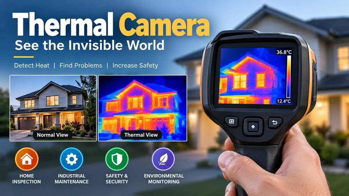

Heat is everywhere, but human eyes cannot see it. A warm electrical connection, missing insulation behind a wall, an overheating bearing, or a person standing in complete darkness may all be difficult to detect visually. A thermal camera makes these temperature patterns visible by detecting infrared radiation rather than ordinary visible light.
A thermal camera is a non-contact imaging device that detects infrared energy emitted or reflected by surfaces and converts it into a visible thermal image. Depending on the model, it can show relative heat patterns or provide calibrated temperature measurements. Thermal cameras are widely used for electrical inspections, building diagnostics, industrial maintenance, research, firefighting, and security.
What Is a thermal camera?
A thermal camera, also called a thermal imager, infrared camera, or infrared thermal imaging camera, is a device designed to visualize differences in thermal energy.
A conventional digital camera records visible light reflected from objects. Thermal imaging works differently. It detects wavelengths of infrared radiation that human eyes cannot see and translates the detected energy into an electronic image.
The resulting picture is commonly called a:
- Thermal image
- Thermogram
- Infrared image
- Heat map
Warmer and cooler areas can be displayed using different shades or colors. The exact colors depend on the selected palette; they are a visualization aid rather than the actual color of infrared radiation.
A crucial distinction is that seeing a thermal pattern and measuring an accurate temperature are not necessarily the same thing. Imaging-only systems may primarily reveal relative differences, while radiometric cameras are calibrated to calculate temperature values.
How Does a thermal camera Work?
Every object above absolute zero emits electromagnetic radiation. The characteristics and intensity of that radiation depend partly on its temperature and surface properties.
Thermal imaging systems detect a portion of this radiation in the infrared spectrum.
The process can be simplified into five steps:
- Infrared energy leaves or reflects from the target surface.
- An infrared-compatible lens collects and focuses that energy.
- A detector array measures the incoming radiation.
- Electronics convert detector responses into digital data.
- Processing software turns those data into a visible thermal image and, for radiometric systems, estimated surface temperatures.
This is fundamentally different from normal photography.
Visible camera vs. thermal camera
| Feature | Thermal camera | Regular camera |
|---|---|---|
| Detects | Infrared radiation | Visible light |
| Image represents | Thermal patterns/apparent surface temperatures | Visible appearance |
| Works in complete darkness | Yes, for thermal targets | Usually requires illumination |
| Measures temperature | Radiometric models can | No |
| Typical resolution | Relatively low | Usually much higher |
| Main uses | Inspection, diagnostics, monitoring | Photography, video, documentation |
Thermal sensors commonly have fewer pixels than visible-light sensors. Infrared wavelengths are longer than visible wavelengths, and detector architecture differs substantially from ordinary imaging sensors.
Infrared Radiation and the Science Behind Thermal Imaging
Infrared radiation lies outside the visible portion of the electromagnetic spectrum.
Human vision covers only a relatively narrow wavelength range. Infrared extends beyond visible red light and includes multiple bands used for different sensing applications.
Two particularly important regions in thermal imaging are:
- MWIR — mid-wave infrared: approximately 3–5 µm
- LWIR — long-wave infrared: approximately 8–14 µm
Many general-purpose uncooled thermal cameras operate in the LWIR region. High-performance cooled systems are often designed for MWIR applications, although the exact architecture depends on the application.
What is a microbolometer?
A microbolometer is a detector technology commonly found in uncooled thermal cameras.
Instead of operating like an ordinary CMOS photography sensor, its detector elements respond to incoming infrared energy. Changes at individual detector pixels are converted into electrical signals and processed to form an image.
Uncooled microbolometer systems can operate near ambient temperature, which helps make them compact and practical for handheld cameras, smartphones, inspection equipment, and fixed monitoring systems.
What Can a thermal camera See?
A thermal camera primarily shows surface thermal patterns.
For example, it may reveal:
- An unusually hot electrical terminal
- Heat escaping around a window
- An overheating motor bearing
- Uneven heating in machinery
- A person or animal at night
- A warm pipe behind certain materials
- Moisture-related thermal anomalies
- Insulation deficiencies
- Temperature differences across electronic components
This capability is why infrared thermography has become valuable for condition monitoring and preventive maintenance. Technicians can inspect operating equipment without necessarily touching the component being examined.
But thermal imaging should not be treated as literal X-ray vision.
Can a thermal camera See Through Walls?
No. A thermal camera does not normally see through walls.
It primarily detects infrared radiation reaching the camera from a surface.
What makes thermal imaging useful in building inspections is that something behind a wall may change the surface temperature of the wall itself.
Imagine that insulation is missing inside one section of an exterior wall. Heat transfer may cause that section of drywall to have a different surface temperature from surrounding areas.
The camera detects that difference.
It is therefore more accurate to say:
A thermal camera can reveal surface heat patterns caused by conditions behind a wall, but it does not directly see through the wall.
The same principle applies when locating some pipes, air leaks, insulation problems, and moisture-related anomalies.
What about glass?
Ordinary glass can create another misconception.
A thermal camera operating in common long-wave infrared bands generally does not look through normal window glass the way a visible-light camera does. Depending on wavelength and material, the camera may instead detect radiation emitted or reflected by the glass surface.
That is why a thermal image of a window should not automatically be interpreted as a thermal view of everything on the other side.
Why Thermal Images Use Different Colors
Thermal radiation itself does not arrive as the familiar rainbow-like image displayed on a thermal camera screen.
The camera assigns colors or grayscale values to different signal or temperature levels.
Common palettes include:
- White hot
- Black hot
- Iron-style palettes
- Rainbow
- High contrast
- Grayscale
Suppose a scene ranges from 20°C to 80°C. Image-processing software can map cooler areas to dark shades and progressively warmer areas to brighter shades.
Changing the palette does not change the object’s temperature. It changes how the information is presented.
This matters in professional inspections because a visually dramatic red area does not automatically mean something is dangerously hot. Always read the measurement scale and compare the component against appropriate operating conditions.
Thermal Imaging vs. Infrared Thermometer
A thermal camera and an infrared thermometer use related principles, but they provide very different information.
| Feature | Thermal camera | Infrared thermometer |
|---|---|---|
| Thermal image | Yes | No |
| Temperature pattern | Yes | No |
| Area inspection | Excellent | Limited |
| Spot measurement | Usually available | Yes |
| Detects unexpected hotspots | Easier | Requires aiming at the right location |
| Data per inspection | Potentially thousands of measurement pixels | Usually one measurement area |
An infrared thermometer is useful when you already know exactly where to measure.
A thermal imager is more useful when the location of the problem is unknown.
For example, pointing a thermometer at one terminal in an electrical panel provides a temperature reading for that target. A thermal image can reveal that another connection elsewhere in the panel is unexpectedly hotter.
Radiometric vs. Non-Radiometric Thermal Imaging
One specification that is easy to overlook is radiometry.
Non-radiometric imaging
A non-radiometric camera produces an image representing relative infrared intensity or thermal differences.
This can be sufficient when the goal is detection—for example, determining whether a person or vehicle is present.
Radiometric thermal imaging
A radiometric thermal camera goes further by associating image data with calibrated apparent temperature measurements.
Producing useful measurements requires accounting for factors such as:
- Emissivity
- Reflected apparent temperature
- Target distance
- Atmospheric temperature
- Relative humidity
- Transmission through an external infrared window, if present
Professional systems may store measurement information with the image so it can be analyzed later.
Emissivity: The Specification People Often Ignore
Emissivity describes how effectively a surface emits thermal radiation compared with an ideal blackbody at the same temperature.
Its theoretical scale runs from 0 to 1.
High-emissivity materials generally make infrared temperature measurement easier. Low-emissivity surfaces, especially shiny metals, can produce misleading readings because reflected radiation contributes significantly to what reaches the detector.
For perspective, human skin and water are around 0.98 emissivity, while highly polished copper or aluminum may be below 0.10. Many flat paints are around 0.90.
Why shiny metal causes problems
Imagine pointing a thermal camera toward a polished metal surface.
A bright or warm-looking region might not represent the metal’s actual temperature. The surface may be reflecting infrared radiation from:
- Your body
- Nearby machinery
- A heater
- The sky
- Other hot equipment
This is one of the most common thermal-imaging interpretation mistakes.
When accurate temperature measurement matters, proper emissivity settings and reflected-temperature compensation become essential.
Thermal Resolution: Why Pixel Count Matters
Thermal resolution describes the number of detector pixels available to create the infrared image.
Examples include:
- 80 × 60
- 160 × 120
- 240 × 180
- 320 × 240
- 640 × 480
- 640 × 512
- 1280 × 1024
Higher resolution generally provides more spatial detail and places more measurement pixels on smaller or more distant targets.
For example, FLIR’s current professional ranges illustrate how widely specifications can vary: some compact systems use 160 × 120 sensors, while higher-level systems provide 320 × 240, 464 × 348, or 640 × 480 thermal resolution.
But resolution alone does not determine image quality.
What Is NETD or Thermal Sensitivity?
Another critical specification is NETD, or Noise Equivalent Temperature Difference.
It is normally expressed in millikelvins (mK) and describes the detector’s ability to distinguish small temperature differences from noise.
A lower NETD is generally better.
For example:
- 60 mK — less sensitive
- 50 mK — better
- 30 mK — more sensitive
This does not mean a 30 mK camera necessarily has ±0.03°C measurement accuracy.
Sensitivity and accuracy are different specifications.
NETD relates to the ability to resolve subtle thermal differences. Measurement accuracy describes how close the reported temperature is expected to be to the actual temperature under specified conditions.
This distinction matters when comparing cameras.
A highly sensitive imager may produce clearer details in low-contrast scenes even when another model has similar pixel resolution.
Field of View and Detection Distance
Field of view (FOV) describes how much of a scene the camera sees through its lens.
A wide field of view is useful for:
- Indoor building inspections
- Electrical panels
- Close-range machinery
- Large surfaces at short distances
A narrow field of view places more pixels on distant targets, which can be useful for long-range inspection and surveillance.
How far can a thermal camera see?
There is no universal maximum distance.
The useful distance depends on factors including:
- Detector resolution
- Lens
- Field of view
- Target size
- Target-to-background temperature difference
- Atmospheric conditions
- Required task
- Measurement spot size
There is also an important distinction between detecting, recognizing, identifying, and accurately measuring a target.
A camera might detect a warm object at considerable distance without providing enough pixels to identify fine details or accurately measure its temperature.
For temperature measurement, FLIR recommends having at least a 3 × 3 pixel area on the target and ensuring the target overfills the measurement spot.
Quick Takeaway: Being able to see an object in a thermal image does not automatically mean the camera can accurately measure its temperature.
Cooled vs. Uncooled Thermal Cameras
Thermal imaging systems can broadly be divided into cooled and uncooled detector technologies.
Uncooled thermal cameras
These are common in:
- Building inspections
- Electrical maintenance
- HVAC work
- Handheld inspection tools
- Security
- Smartphone thermal imaging
Many use microbolometer detectors and operate near ambient temperature.
Advantages include:
- Smaller size
- Lower complexity
- Lower cost
- Less maintenance
- Convenient portable operation
Cooled thermal cameras
High-performance detectors may be cooled cryogenically, sometimes to roughly 77 K depending on the technology.
Cooled systems can provide greater sensitivity and support demanding applications involving subtle or fast thermal events.
The trade-offs are significant:
- Greater cost
- More complexity
- Increased size and weight
- Cooler maintenance requirements
That makes cooled systems particularly relevant to scientific research, aerospace, specialized industrial work, and other demanding measurement applications rather than routine home inspection.
Common Uses of a thermal camera
The usefulness of thermal imaging comes from one simple capability: detecting temperature patterns without requiring physical contact with the target.
Electrical inspections
Electrical technicians use thermal cameras to identify abnormal heating in components such as:
- Breakers
- Fuses
- Busbars
- Connections
- Switchgear
- Transformers
- Cables
- Terminals
An unusually warm connection can indicate increased resistance, excessive load, imbalance, or another condition requiring investigation.
Thermal imaging is particularly valuable because energized equipment can often be observed under normal load without touching the component.
However, a thermal anomaly is evidence for further investigation—not automatically a diagnosis.
Building inspections and energy audits
Thermography can reveal surface patterns associated with:
- Missing insulation
- Thermal bridging
- Air leakage
- HVAC problems
- Window and door losses
- Roof anomalies
- Moisture-related temperature differences
Timing matters.
If indoor and outdoor temperatures are nearly identical, an insulation defect may produce little thermal contrast. Appropriate environmental conditions can make the same defect much easier to detect.
HVAC systems
Heating, ventilation, and air-conditioning professionals can use thermal imaging to examine:
- Supply and return air patterns
- Radiators
- Underfloor heating
- Refrigeration equipment
- Ductwork
- Coils
- Compressors
- Electrical components
The resulting thermal pattern can help narrow down where additional testing should be performed.
Industrial preventive maintenance
Motors, bearings, pumps, conveyor systems, electrical cabinets, and production equipment often develop abnormal heat patterns before obvious failure.
Repeated thermal inspections can therefore support condition monitoring and predictive or preventive maintenance.
The strongest approach is usually trending rather than relying on one isolated image.
A component at 65°C, for example, cannot automatically be labeled defective. Its load, ambient conditions, design, comparable components, and historical measurements all matter.
Electronics
Thermal imaging is useful for examining:
- Printed circuit boards
- Power supplies
- Batteries
- Voltage regulators
- Processors
- Connectors
- Charging circuits
A high-resolution, low-NETD camera can be especially useful when temperature differences are small and components are physically close together.
Firefighting and search operations
Specialized thermal imaging can help firefighters locate heat signatures through smoke and identify hotspots that remain after visible flames have been suppressed.
Thermal imaging can also support search-and-rescue operations because a person may remain thermally distinguishable from their surroundings even when visible-light conditions are poor.
Security and surveillance
Unlike ordinary cameras, thermal systems do not depend on visible illumination.
That makes them useful for detecting people, animals, and vehicles in:
- Darkness
- Low-contrast scenes
- Perimeter monitoring
- Remote areas
The purpose here is often detection rather than temperature measurement, so radiometric capability may not be required.
Can a thermal camera Work in Complete Darkness?
Yes.
A thermal camera does not need visible light to form a thermal image because it detects infrared energy rather than reflected visible illumination.
This gives thermal imaging an advantage over ordinary cameras in nighttime environments.
However, darkness does not eliminate other limitations. Fog, rain, humidity, atmospheric absorption, target distance, lens choice, and low thermal contrast can still affect performance.
A person standing against a background at nearly the same apparent temperature may be harder to distinguish than someone with strong thermal contrast against their surroundings.
What Determines Thermal Measurement Accuracy?
Accurate thermography involves considerably more than pointing the camera at an object.
Important variables include:
1. Emissivity
Incorrect emissivity settings can create substantial errors, especially on reflective surfaces.
2. Reflected apparent temperature
Infrared radiation from surrounding objects can reflect from the target into the camera.
3. Distance
The atmosphere between the target and camera affects the radiation reaching the detector, particularly over longer distances.
4. Relative humidity
Water vapor influences infrared transmission through the atmosphere.
5. Atmospheric temperature
Air temperature is another parameter used by professional measurement systems when compensating for atmospheric effects.
6. Focus
A poorly focused thermal image is not merely unattractive. It can affect measurement quality by spreading the target’s energy across pixels.
7. Target size
The target must occupy enough detector pixels for reliable measurement.
8. Viewing angle
Highly reflective surfaces can produce dramatically different apparent thermal patterns as the viewing angle changes.
These factors explain why professional thermography requires both appropriate equipment and knowledgeable interpretation.
Thermal Camera Specifications Explained
When evaluating the capability of any thermal imaging system, these specifications provide a much better picture than resolution alone.
| Specification | What It Tells You |
|---|---|
| IR resolution | Number of thermal detector pixels |
| NETD | Ability to resolve small temperature differences |
| Temperature range | Temperatures the instrument is designed to measure |
| Accuracy | Expected measurement uncertainty under stated conditions |
| Field of view | Width of scene captured |
| IFOV/spatial resolution | Area represented by an individual detector pixel |
| Spectral range | Infrared wavelengths detected |
| Focus | Ability to optimize image sharpness for distance |
| Radiometry | Whether calibrated temperature data are available |
| Frame rate | How frequently images are updated |
Professional instruments illustrate why these numbers need to be considered together. For example, current radiometric systems may specify measurement accuracy around ±2°C or ±2% under defined operating conditions while having NETD values below 30–60 mK depending on the camera and lens. Those numbers describe different aspects of performance.
Common Thermal Imaging Mistakes
Owning a high-quality thermal camera does not automatically produce reliable conclusions.
Several mistakes appear repeatedly in real-world inspections.
Treating every hot spot as a fault
Hot does not necessarily mean defective.
Electrical load, friction, environmental heating, component design, and normal operating conditions can all produce legitimate temperature differences.
Compare similar components operating under similar loads whenever possible.
Ignoring emissivity
This is especially problematic with polished metals.
The apparent temperature shown on screen may be heavily influenced by reflected radiation rather than the actual surface temperature.
Confusing NETD with accuracy
A low NETD means the detector can distinguish smaller thermal differences. It does not mean absolute temperature readings are accurate to that same tiny value.
Measuring a target that is too small
Seeing a target and measuring it reliably are different tasks.
If the target occupies too few detector pixels, surrounding background energy can influence the reading.
Assuming thermal imaging finds moisture directly
A thermal camera does not directly measure water content.
Evaporation and heat-transfer differences can create thermal patterns associated with moisture. Those patterns should normally be confirmed using an appropriate moisture meter or another diagnostic method.
Ignoring environmental conditions
Sunlight can warm exterior building materials long after direct exposure ends. Wind can cool surfaces. Rain changes temperatures. Nearby heaters affect reflections.
Good thermography considers the environment as part of the measurement.
Advantages of Thermal Imaging
Thermal cameras offer several practical advantages.
Non-contact inspection: Hot, moving, elevated, or otherwise difficult targets can often be examined from a safer distance.
Large-area visualization: Instead of checking one location at a time, a thermal image reveals temperature patterns across the whole field of view.
Operation without visible light: Thermal imaging can detect suitable targets in complete darkness.
Fast anomaly detection: Unexpected hot or cold areas can stand out immediately.
Documentation: Radiometric images can preserve thermal data for reporting, trending, and later analysis.
Preventive maintenance: Repeated inspections can help identify developing anomalies before equipment failure.
These strengths explain why thermography is used across building science, electrical maintenance, manufacturing, research, public safety, and surveillance.
Limitations of a thermal camera
Thermal imaging is powerful, but understanding its limitations is essential.
A thermal camera generally:
- Cannot see through ordinary solid walls
- Does not operate like an X-ray
- Does not directly measure moisture
- Cannot automatically determine why something is hot
- Can be confused by reflective surfaces
- May give inaccurate temperatures with incorrect settings
- Has lower resolution than many visible-light cameras
- Can be affected by environmental and atmospheric conditions
- Requires sufficient pixels on a target for dependable measurements
Most importantly, a thermogram needs context.
A bright hotspot is an observation. Determining whether it represents a loose electrical connection, expected load, reflected radiation, mechanical friction, or another cause requires inspection knowledge and often additional testing.
How to Read a Thermal Image Correctly
A useful thermal inspection follows a repeatable process.
- Understand the equipment or structure being inspected.
- Check environmental conditions before measuring.
- Choose a suitable thermal range and image span.
- Focus the image carefully.
- Set appropriate emissivity when temperature accuracy matters.
- Account for reflected apparent temperature where necessary.
- Make sure the target is large enough in the image.
- Compare similar components under comparable conditions.
- Record relevant load and environmental information.
- Confirm suspicious findings using another appropriate diagnostic method.
The last step is especially important.
If thermal imaging suggests moisture, verify it with moisture-testing equipment. If an electrical connection appears unusually hot, appropriate electrical tests and physical inspection can help determine the cause.
Thermography works best as part of a diagnostic process rather than as a standalone answer.
What Features Matter Most in a Thermal Camera?
There is no single specification that defines a good thermal imager.
The right capability depends on the job.
For close-range home inspection, a wide field of view may be more useful than extreme detection distance. Electronics inspection may benefit greatly from higher spatial resolution, close-focus capability, and low NETD. Long-distance inspection requires enough pixels on the target and suitable optics.
For measurement-focused work, pay particular attention to:
- Thermal resolution
- NETD
- Measurement accuracy
- Temperature range
- Field of view
- Minimum focus distance
- Radiometric capability
- Emissivity adjustment
- Reflected-temperature compensation
- Image storage and reporting capability
For detection-focused applications such as surveillance, priorities may shift toward range, frame rate, field of view, durability, and reliable target detection.
Thermal Imaging, Thermography, and Heat Maps: Are They the Same?
The terms overlap but are not perfectly interchangeable.
Thermal imaging refers broadly to creating images from infrared thermal radiation.
Infrared thermography generally refers to the science and practice of using thermal imaging to analyze temperature patterns and, where applicable, perform temperature measurements.
A thermogram is the resulting thermal image.
A heat map is a broader visualization term. Many kinds of data can be displayed as heat maps, so not every heat map is an infrared thermogram.
Passive thermography observes naturally occurring thermal patterns, while active thermography deliberately introduces thermal stimulation and observes how the target responds. Active techniques can help reveal defects that might not be obvious from equilibrium surface temperatures alone.
The Bottom Line
A thermal camera extends human vision into the infrared spectrum. Instead of photographing visible light, it detects infrared energy and converts temperature-related differences into an image that can reveal patterns invisible to the naked eye.
Its real value is not simply finding things that look “hot.” Proper thermal imaging combines detector resolution, thermal sensitivity, field of view, radiometry, emissivity, reflected temperature, environmental conditions, and informed interpretation.
For building diagnostics, electrical inspections, industrial maintenance, electronics, firefighting, research, or security, the same principle applies: use the thermal image to identify an anomaly, understand the conditions that produced it, and verify important findings with the appropriate complementary method.
