

A computer may perform millions or billions of operations every second, but its basic working process is surprisingly easy to understand. Data enters through an input device, gets processed according to instructions, may be stored in memory, and finally appears as useful output.
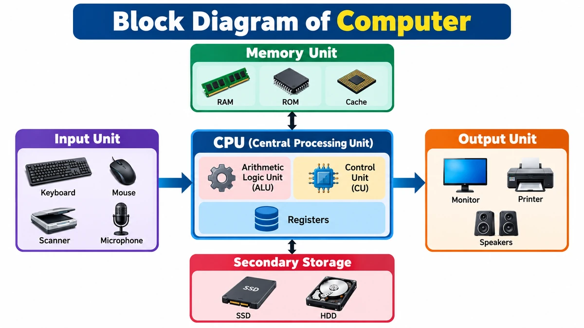
A block diagram of computer is a simplified visual representation of these major functional units and the way data, instructions, and control signals move between them. The main blocks are the Input Unit, Central Processing Unit (CPU), Memory Unit, and Output Unit. Inside the CPU, the Arithmetic Logic Unit (ALU), Control Unit (CU), and registers work together to execute instructions.
Block Diagram of Computer
A basic block diagram can be represented as:
                    +----------------------+
                    |     Memory Unit      |
                    |  RAM / ROM / Cache   |
                    +----------+-----------+
                               ↕
+-------------+       +--------+---------+       +-------------+
|             |       |                  |       |             |
| Input Unit  | ----> |       CPU        | ----> | Output Unit |
|             |       |                  |       |             |
+-------------+       |  +------------+  |       +-------------+
                      |  | Control    |  |
                      |  | Unit (CU)  |  |
                      |  +------------+  |
                      |                  |
                      |  +------------+  |
                      |  |    ALU     |  |
                      |  +------------+  |
                      |                  |
                      |  +------------+  |
                      |  | Registers  |  |
                      |  +------------+  |
                      +--------+---------+
                               ↕
                    +----------+-----------+
                    | Secondary Storage   |
                    | SSD / HDD / Other   |
                    +----------------------+
The diagram represents the basic Input → Processing → Output model. Memory supports processing by holding programs, data, intermediate values, and results, while storage keeps information for longer-term use.
Main Components of Block Diagram of Computer
The major functional units are:
| Component | Main Function | Common Examples |
|---|---|---|
| Input Unit | Accepts data and instructions | Keyboard, mouse, scanner |
| CPU | Processes instructions and controls operations | Processor |
| ALU | Performs arithmetic and logical operations | Part of CPU |
| Control Unit | Coordinates instruction execution | Part of CPU |
| Registers | Hold immediate working data | CPU registers |
| Memory Unit | Stores active data and instructions | RAM, ROM, cache |
| Secondary Storage | Stores data for long-term use | SSD, HDD |
| Output Unit | Presents processed information | Monitor, printer, speakers |
These units do not operate independently. They continuously exchange data and control information to complete tasks. Educational computer-architecture diagrams commonly show CPU, memory, input, and output as interconnected functional blocks.
1. Input Unit
The input unit is the starting point of data processing. It provides a way for data and instructions to enter a computer system.
Common input devices include:
- Keyboard
- Mouse
- Scanner
- Microphone
- Webcam
- Touchscreen
- Barcode reader
- Joystick
Suppose you type 25 + 15 using a keyboard. The keyboard provides the characters as input. The computer represents that input internally in machine-readable form so that it can be stored and processed.
Functions of the Input Unit
The input unit performs three basic jobs:
- Accepts data and instructions.
- Converts or encodes input into a representation the computer can process.
- Transfers that information toward memory or the processing system.
The input unit therefore acts as an interface between an external source—often the user—and the internal components of the computer.
2. Central Processing Unit (CPU)
The Central Processing Unit, commonly called the CPU, executes program instructions and coordinates many of the operations taking place in a computer.
A simplified CPU is commonly explained using three important elements:
- Arithmetic Logic Unit (ALU)
- Control Unit (CU)
- Registers
The CPU communicates with memory and input/output hardware while executing instructions. Modern processors are considerably more complex than a basic educational block diagram suggests, but these functional concepts remain useful for understanding computer organization.
3. Arithmetic Logic Unit (ALU)
The Arithmetic Logic Unit, or ALU, is responsible for arithmetic and logical operations.
Arithmetic Operations
Typical arithmetic operations include:
- Addition
- Subtraction
- Multiplication-related operations
- Division-related operations
- Incrementing and decrementing values
Logical Operations
The ALU also handles operations involving logic and comparisons, such as:
- AND
- OR
- NOT
- XOR
- Equal to
- Greater than
- Less than
For example, if a program needs to compare two numbers to determine which is larger, processor logic performs the required comparison.
The ALU works closely with CPU registers and the control unit. Registers can supply operands to an operation and temporarily hold its result.
4. Control Unit (CU)
The Control Unit, abbreviated as CU, coordinates instruction execution and the activities of other functional components.
Rather than performing the arithmetic calculation itself, the control unit directs operations by generating appropriate control signals.
Its responsibilities include:
- Fetching instructions
- Interpreting or decoding instructions
- Coordinating their execution
- Directing movement of data
- Sending control signals
- Coordinating CPU, memory, and I/O operations
Think of the control unit as the coordinator of the processing cycle. It determines which operations need to happen and helps ensure that the appropriate parts of the system perform them in the required sequence.
Educational computer architecture material describes the CU as controlling and coordinating the computer’s operations, including the sequence in which instructions execute.
5. Registers
Registers are very small, fast storage locations associated with the CPU. They temporarily hold values needed immediately during instruction execution.
They may hold:
- Data being processed
- Instructions
- Memory addresses
- Intermediate calculation results
For example, when the ALU performs an operation, the values involved may be placed in registers. The result may also be placed in a register before being written elsewhere.
This is why registers should not be confused with normal file storage. Their purpose is immediate processor work rather than long-term storage.
6. Memory Unit
The memory unit stores data and instructions required by the computer.
At an introductory level, computer storage is often divided into primary memory and secondary storage.
Primary Memory
Primary memory is closely involved in active computer operations. Important examples include RAM and ROM, while cache is another critical form of fast memory used close to the processor.
RAM
Random Access Memory (RAM) provides working space for programs and data currently being used.
RAM is volatile, which means its contents normally disappear when power is removed.
For example, when you open a web browser or document editor, active program data can be held in RAM while the application is running.
ROM
Read-Only Memory (ROM) is non-volatile memory used for information that needs to persist without normal electrical power.
ROM technologies and their exact uses vary by computer system, so it is better understood as a category of non-volatile memory rather than simply as a place for ordinary user files.
Cache Memory
Cache memory provides high-speed storage close to or within the processor. It helps reduce the delay involved in repeatedly accessing frequently needed instructions or data from slower levels of memory.
Secondary Storage
Secondary storage provides longer-term storage for programs and files.
Examples include:
- Solid-state drives (SSDs)
- Hard disk drives (HDDs)
- USB flash drives
- Memory cards
- Optical media
Unlike ordinary RAM, SSDs and HDDs retain stored information when power is switched off.
7. Output Unit
The output unit communicates processed information to the outside world.
Common output devices include:
- Monitor
- Printer
- Speakers
- Headphones
- Projector
For example, after a computer calculates 25 + 15, the result 40 can be displayed on the monitor.
Functions of the Output Unit
The output unit generally:
- Receives processed results from the computer.
- Presents or converts those results into an appropriate external form.
- Delivers the information through an output device.
Input and output units therefore form the major interfaces through which a computer exchanges information with users and other systems.
How Does the Block Diagram of Computer Work?
Understanding the individual components is useful, but the block diagram becomes much clearer when you follow data through the complete process.
Consider a simple example: calculating 25 + 15.
Step 1: Input Is Entered
The user enters:
25 + 15using a keyboard or another input interface.
Step 2: Data and Instructions Become Available for Processing
The required data and program instructions are placed where the processor can access them, typically involving main memory.
Step 3: CPU Fetches the Instruction
The CPU obtains the next instruction required by the program.
Step 4: Control Unit Decodes It
The control unit interprets what operation needs to be performed and coordinates the required internal actions.
Step 5: ALU Performs the Operation
The appropriate values are supplied for processing, and the ALU performs the arithmetic operation:
25 + 15 = 40Step 6: Result Is Stored
The result can be held temporarily in a register or memory and, when required, written to longer-term storage.
Step 7: Output Is Produced
The result is sent to an output device.
40appears on the screen.
This simplified sequence illustrates how input, memory, CPU, and output cooperate rather than functioning as isolated components.
Input-Process-Output Cycle
One of the easiest ways to remember the working of a computer is the IPO cycle:
Input → Process → OutputStorage can support each stage:
Input → Memory → Processing → Memory → OutputSuppose you edit a photograph:
- Input: The image file and your editing commands enter the application.
- Processing: The CPU and, depending on the workload, other processors perform calculations.
- Memory: Active image data and program instructions are kept available during editing.
- Output: The edited image appears on the display.
- Storage: The finished file can be saved to an SSD or another storage device.
The same basic concept applies to many computing tasks even though real systems may execute huge numbers of operations simultaneously or in rapid succession.
How CPU, Memory, and I/O Communicate
A basic block diagram shows the major functional units, but it is also useful to understand what connects them.
Computer components communicate through interconnection mechanisms commonly described as buses.
Three traditional categories are:
Data Bus
The data bus carries data between components such as the processor, memory, and I/O interfaces.
Address Bus
The address bus is associated with identifying the memory or I/O location involved in an operation.
Control Bus
The control bus carries signals used to coordinate operations, such as read/write and other control functions.
Together, these communication paths allow the processor and other system components to exchange information in an organized way. Computer architecture diagrams commonly distinguish data/instruction movement from control signals.
Data Flow vs. Control Flow
A useful distinction when reading a block diagram of computer is the difference between data flow and control flow.
Data flow describes the movement of data, instructions, addresses, and results among functional units.
Control flow, in this context, refers to signals that coordinate what different components should do.
For example, a value moving from memory toward the CPU represents data movement. A signal directing memory to perform a read operation is a control action.
Some educational diagrams use different arrow styles to distinguish data/instruction paths from control signals.
CPU vs. Memory Unit
CPU and memory are closely connected, but they perform different jobs.
| CPU | Memory Unit |
|---|---|
| Executes instructions | Stores data and instructions |
| Performs calculations and logic | Supplies information needed for processing |
| Contains ALU and control logic | Includes different memory technologies |
| Uses registers for immediate working values | Provides larger storage capacity than registers |
| Coordinates instruction execution | Retains information for different periods depending on memory type |
A simple way to remember the difference is:
Memory holds what is needed; the CPU performs the work described by instructions.
Primary Memory vs. Secondary Storage
These concepts are often confused in introductory computer lessons.
| Feature | Primary Memory | Secondary Storage |
|---|---|---|
| Main purpose | Active working data/instructions | Long-term data storage |
| Examples | RAM, ROM | SSD, HDD |
| CPU relationship | Closely involved in processing | Generally accessed through storage/I/O mechanisms |
| Capacity | Usually smaller | Usually larger |
| Persistence | Depends on memory type | Normally non-volatile |
| Typical speed | Faster than mass storage | Slower than primary working memory |
One common mistake is to say that all primary memory is temporary. That is not accurate because ROM is non-volatile. RAM is the primary-memory example that normally loses its contents when power is removed.
What Is the Fetch-Decode-Execute Cycle?
The basic CPU operation is often explained using the fetch-decode-execute cycle.
Fetch
The processor obtains an instruction from memory.
Decode
The control logic interprets the instruction and determines the required operation.
Execute
The CPU carries out the instruction. This might involve an ALU calculation, a data transfer, a comparison, or another processor operation.
The result may then be written to a register or memory.
This cycle repeats continuously while programs execute. It provides a more detailed view of what happens inside the “processing” block of a simple Input → Process → Output diagram.
Why Is the Block Diagram of Computer Important?
The block diagram simplifies a complex electronic system into functional parts that are easier to understand.
It helps students understand:
- Where input enters the system
- Where instructions are processed
- Why memory is necessary
- What the ALU does
- What the control unit does
- How results reach output devices
- How major computer components communicate
It also creates a foundation for studying more advanced subjects such as computer organization, computer architecture, operating systems, microprocessors, memory hierarchy, and digital electronics.
How to Draw a Block Diagram of Computer
For an exam or classroom assignment, begin with the four essential functional areas.
Step 1: Draw the Input Unit
Place the Input Unit on the left.
[ Input Unit ]Step 2: Draw the CPU
Place the CPU in the center and show the ALU and Control Unit inside it.
+------------------+
|       CPU        |
|  +------------+  |
|  |    ALU     |  |
|  +------------+  |
|  |     CU     |  |
|  +------------+  |
+------------------+
You can also show registers inside the CPU for a more complete diagram.
Step 3: Add the Memory Unit
Place memory near the CPU and connect it using two-way arrows to represent the exchange of information.
Step 4: Draw the Output Unit
Place the Output Unit on the right.
[ CPU ] ----> [ Output Unit ]Step 5: Add Secondary Storage
For a more detailed version, add an SSD/HDD or a general Secondary Storage block.
Step 6: Connect the Blocks
Use arrows to show the major relationships among input, memory, CPU, storage, and output.
A good diagram should be simple enough to understand at a glance rather than overloaded with hardware details.
Simple Block Diagram of Computer for Exams
For a short-answer question, this simplified version is usually enough to communicate the core concept:
                     +----------------+
                     |  Memory Unit   |
                     +-------+--------+
                             ↕
+------------+       +-------+-------+       +-------------+
| Input Unit | ----> |      CPU      | ----> | Output Unit |
+------------+       |  ALU + CU     |       +-------------+
                     +---------------+
When explaining it, state that the input unit supplies data and instructions, memory stores information needed during processing, the CPU executes instructions, and the output unit presents the resulting information.
Common Mistakes When Drawing the Diagram
A block diagram looks simple, but several mistakes can make an answer incomplete.
Putting the ALU Outside the CPU
In the standard introductory model, the ALU is shown as a component of the CPU.
Forgetting the Control Unit
The CPU does more than calculations. The CU coordinates instruction execution and operations across the system.
Treating RAM and SSD as the Same Thing
RAM is active working memory and is normally volatile. An SSD provides persistent secondary storage.
Showing Only One-Way Communication with Memory
CPU and memory exchange information, so introductory diagrams commonly represent their relationship using bidirectional communication.
Forgetting Registers
Very simple diagrams may omit registers, but including them provides a better representation of the CPU’s immediate working storage.
Confusing Input with Output
A keyboard and mouse primarily provide input. A monitor and printer primarily provide output. Some devices, such as touchscreens, can perform both roles.
Block Diagram vs. Physical Computer Hardware
A block diagram is a functional abstraction, not a literal map of the motherboard.
For example, the “Memory Unit” block may represent a category of memory functions rather than one physical component. Similarly, the CPU block hides substantial internal complexity.
Modern processors may include:
- Multiple CPU cores
- Several cache levels
- Branch prediction
- Instruction pipelines
- Memory controllers
- Vector or specialized execution units
Modern computers can also include GPUs and dedicated accelerators.
The basic block diagram deliberately hides these details. Its purpose is to explain the fundamental relationship among input, processing, memory, storage, and output, rather than reproduce every circuit inside a modern computer.
Practical Example of the Block Diagram of Computer
Imagine typing a sentence into a text editor.
First, the keyboard provides input. The computer receives information corresponding to the keys you press.
The operating system and application process those events. Relevant program instructions and working data are maintained in memory.
The CPU executes the required instructions. Its control logic coordinates operations, registers hold immediate values, and processing units perform the necessary operations.
The monitor then displays the characters as output.
When you save the document, the information is written to secondary storage, such as an SSD.
The complete process can therefore be summarized as:
Keyboard
   ↓
Input
   ↓
Memory ↔ CPU
   ↓
Display Output
   ↓
SSD when the file is saved
This simple example demonstrates why each block matters. Remove input and the system cannot receive your typing. Remove processing and the instructions cannot be executed. Remove working memory and normal program execution becomes impossible. Remove output and the user cannot see the displayed result.
Final Summary
The block diagram of computer provides a simple way to understand how a computer accepts, processes, stores, and returns information.
Its main functional components are the Input Unit, CPU, Memory Unit, Secondary Storage, and Output Unit. Within the CPU, the Control Unit coordinates instruction execution, the ALU performs arithmetic and logical operations, and registers provide fast temporary working storage.
The entire process can be remembered through the basic pattern:
Input → Processing ↔ Memory → Output
Secondary storage adds long-term retention of programs and files. Although real computers are much more complex, this functional model remains one of the clearest starting points for understanding computer organization and the flow of data through a computer system.
